Product series
:
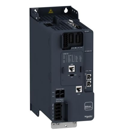
Altivar Machine ATV340
Product or component type
:
Variable Speed Driver
Model
:
Standard type
Assembly type
:
Assembly
Communication Port Protocol
:
Ethernet IP
Modbus Series
MODBUS TCP
Option card
:
Communication Module, Profinet
Communication Module, Devicenet
Communication Module, Canopen
Communication Module, Ethercat
Network Network of Phase
:
3 phases
Feeding frequency
:
50 … 60 Hz – 5
[US] Nominal Nutrition Voltage
:
380 … 480 V – 15 … 10
Nominal output current
:
16.5 A
Motor Power KW
:
Normal condition for 11 kW
Heavy condition for 7.5 kW
Motor Power HP
:
Normal requirement for 15 hp
Heavy condition for 10 hp
IP Protection Class
:
IP20
Complementary features
Number of digital inputs
:
5
Digital entry type
:
Programmable as PTI coup entrance: 0 30 kHz, 24 V dc (30 V)
DI1 … DI5 Secure Torque Closing, 24 V DC (30 V), Impedance: 3.5 Kohm
Programmable
Pre -adjusted speed number
:
16 Pre -adjustable speed
Digital output number
:
2.0
Number of analog inputs
:
2
Analog input type
:
AI1 Software-Related Current: 0 … 20 MA, Impedance: 250 ohm, resolution 12 bit
AI1 Software-Configurable Temperative Probe Or Water Level Sensor
AI1 Software-Related Voltage: 0 … 10 V DC, Impedance: 31.5 Kohm, resolution 12 bit
AI2 Software -Released Voltage: – 10 … 10 V DC, Impedance: 31.5 Kohm, resolution 12 bit
Analog output number
:
2
Analog output type
:
Software-Released Voltage AQ1: 0 … 10 V DC Impedance 470 ohm, resolution 10 bit
Software-Related Current AQ1: 0 … 20 MA Impedance 500 OHM, resolution 10 bit
Relay output number
:
2
Output voltage
:
power feeding voltage
Relay output type
:
Relay outputs R1A
Relay outputs R1C Electrical Resistance 100000 Cycles
Relay outputs R2A
Relay outputs R2C Electrical Durability 100000 Cycles
Maximum switching current
:
Relay output R1C resistant load, cos phi 1: 3 a -de 250 V ac
Relay output R1C resistant load, cos phi 1: 3 a -de 30 V dc
Inductive load on R1C, COS Phi 0.4 and L R 7 MS: 2 A -DE 250 V AC
Inductive load on R1C, COS Phi 0.4 and L R 7 MS: 2 A -DE 30 V DC
Relay output R2C resistant load, cos phi 1: 5 A -de 250 V AC
Relay output R2C resistant load, cos phi 1: 5 a -de 30 V dc
Inductive load on R2C, COS Phi 0.4 and L R 7 MS: 2 A -DE 250 V AC
Inductive load on R2C, COS Phi 0.4 and L R 7 ms: 2 A -DE 30 V DC
Minimum switching current
:
Relay output R1B: 5 MA -DE 24 V DC
Relay output R2C: 5 MA -E 24 V DC
Physical interface
:
2 wire RS 485
Connector type
:
3 RJ45
Access method
:
SLAVE MODBUS RTU
SLAVE MODBUS TCP
Transmission rate
:
4.8 kbit s
9.6 kbit sec
19,2 kbit sec
38.4 kbit s
Transmission frame
:
Rtu
Number of Addresses
:
1 247
Data format
:
8 bit, configurable single, double or without parity
Polarization type
:
No impedance
Asynchronous motor control profile
:
Variable moment standard
Fixed torque standard
Optimum Moment Mode
Synchronous motor control profile
:
RELUCTANCE MOTOR
Fixed magnetic engine
Maximum output frequency
:
0,599 kHz
Acceleration and slowing ramps
:
S, U or customized
Linear Adjustable Separately from 0.01 … 9999 S
Motor slip compensation
:
AUTOMATICS ALL KINDING LOAD
Continuous magnetic engine law is not available
Compressible
Adjustable
Switching frequency
:
2 … 16 khz adjustable
4 … 16 kHz depreciation factor
Nominal switching frequency
:
4 KHz
Braking until it stops
:
With DC Injection
Line flow
:
22.0 A -DE 380 V (Normal Condition)
17.7 A -DE 480 V (Normal Condition)
25.6 A -de 380 V (heavy condition)
20.4 A -DE 480 V (heavy condition)
Line flow
:
25.6 A -de 380 V without line coil (heavy condition)
20.4 A -DE 480 V line coil (heavy condition)
22 A -de 380 V with external line coil (normal condition)
17.7 A with 480 V external line coil (normal condition)
14.6 A -de 380 V External line coil (heavy condition)
12.1 a -de 480 V external line coil (heavy condition)
Maximum input current
:
25.6 A
Maximum output voltage
:
480 V
Visible power
:
480 V in 17 kva (normal condition)
480 V in 17 kva (heavy condition)
Maximum temporary flux m
:
60 s (normal condition) during 26.4
60 s (heavy condition) during 24.8
During 32.4 A 2 S (Normal condition)
During 29.7, 2 S (heavy condition)
Electric connection
:
Screw Terminal, Clamping Capacity: 4 … 6 mm² DC Bar
Screw Terminal, Clamping Capacity: 0.2 … Control for 2.5 mm²
Screw Terminal, Clamping Capacity: 1.5 … 6 mm² engine
Screw Terminal, Clamping Capacity: 2.5 … 6 mm² Line Side for Side
Possible line ISC
:
22 ka
Base load current at high load
:
16.5 A
Low -overload base load current
:
24.0 A
Power distribution in W
:
Natural Convection: 180 W -DE 380 V 4 kHz (heavy condition)
Forced convection: 180 W -DE 380 V 4 kHz (heavy condition)
Natural Convection: 249 W -DE 380 V 4 KHz (Normal Condition)
Forced convection: 249 W -DE 380 V 4 KHz (Normal Condition)
Electric connection
:
DC BARA: Screw Terminal 4 … 6 mm² AWG 12 … AWG 10
Control: Screw terminal 0.2 … 2.5 mm² AWG 24 … AWG 12
Engine: screw terminal 1.5 … 6 mm² AWG 14 … AWG 10
Line side: screw terminal 2.5 … 6 mm² AWG 12 … AWG 10
Protection type
:
Thermal protection: engine
Secure torque closing: engine
Motor Phase Loss: Motor
Thermal protection: driver
Secure torque closing: Driver
Overheating: Driver
Over Current: Driver
Output Overcurrent Between Motor Phase and Earth: Driver
Output Overcurrent Between Motor Phases: Driver
Short-Circuit Between Motor Phase and Earth: Driver
Short Circuit Between Motor Phase: Driver
Motor Phase Loss: Driver
DC Bus Overvoltage: Driver
Line Feeding Excess Tension: Driver
Low Feeding Low Voltage: Driver
Input Supply Loss: Driver
Excepting Limit Speed: Driver
Cutting in the control circuit: drive
Width
:
110.0 mm
Height
:
270.0 mm
Depth
:
234.0 mm
Product weight
:
3.0 kg
Continuous output current
:
Normal requirement for 24 a -de 4 kHz
Heavy condition for 16.5 a -de 4 kHz
Speed Control Devices
Order by WhatsApp
Schneider ATV340U75N4E 7.5KW 400V Ethernet Trifase Speed control device
Variable Speed Drive – 7.5kW- 400V – 3 Phases – Altivar ATV340 Ethernet – SCHNEIDER quality product.
×