The Altiar Process is a variable speed drive for three-phase synchronous and asynchronous motors, specially designed for the following market segments. The Altivar Process 900 series is focused on maximum productivity with exceptional motor control and connectivity.Oil & gasMining, minerals & metalsFood & beverageWater & waste waterIt offers special functionalities for the industrial process segmentsExcellent motor performance on any type of motorTotal control of any kind of coupling in master/slave applicationsNetwork services help ensure operation continuity even in case of connection breakdownWeb server and data logging help reduce downtime through fast troubleshooting and preventive maintenanceVariable Speed DriversAltivar Process ATV900Three-Phase Supply Voltage :380 to 480 V 50/60 Hz

Automation & Control Gear
Order by WhatsApp
Compare
Electric Variable Schneider Speed Drive, 3 kW, 4 kW, 3 Phase, 400 V ac, 6 A, 7.6 A, ATV930 Series – ATV930U40N4
The Altiar Process is a variable speed drive for three-phase synchronous and asynchronous motors, specially designed for the following market segments.
×
Place your order
Based on 0 reviews
Be the first to review “Electric Variable Schneider Speed Drive, 3 kW, 4 kW, 3 Phase, 400 V ac, 6 A, 7.6 A, ATV930 Series – ATV930U40N4”
Related products
-
Automation & Control Gear
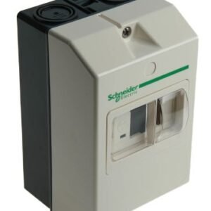
Deca GVAE Schneider Electric Auxiliary Contact, 2 Contact, 2NO, Front Mount, TeSys, TeSys GVAE20
 Automation & Control Gear
Deca GVAE Schneider Electric Auxiliary Contact, 2 Contact, 2NO, Front Mount, TeSys, TeSys GVAE20
Schneider Electric GVAE Series Auxiliary Contact, 2NO Normal State Configuration, Front Mount – GVAE20This auxiliary contact is designed for consistent performance in various applications.
SKU: GVAE20 -
Automation & Control Gear
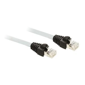
Schneider VW3CANCARR1 – PLC Cable for Use with Altivar 31, Altivar 31C, Altivar 32, Altivar 71, Altivar 312, Altivar Machine
 Automation & Control Gear
Schneider VW3CANCARR1 – PLC Cable for Use with Altivar 31, Altivar 31C, Altivar 32, Altivar 71, Altivar 312, Altivar Machine
The Schneider Electric Accessories are a state of the art design which are used in many areas like the motor control, automation, PLC, Displays, etc.
SKU: VW3CANCARR1
There are no reviews yet.